PIPE FITTINGS

Even with all the advances in technology today, the wholly welded piping system has for decades remained the best choice for use in high pressure and high-temperature applications.

A pipe fitting is any part used in a piping system to change direction or function and joined to that system by some mechanical means or by welding.

Now, with having more than 2 decades of experience in this field and well-trained workmen force, we are capable of satisfying any type of customer requirement. Our Pipe Fittings include all types of elbows, reducers, stub ends, tees, caps, etc.

ELBOW

Since elbows are very commonly used fittings, they will be considered first.

Generally, their size designations are either a long radius or a short radius. The long radius elbow is usually adequate for standard service conditions. The center-to-end dimension is always 1-1/2times the nominal size of the elbow. Short radius elbows have a center-to-end measurement equal to the pipe diameter.

For a particular job, the type of elbow selected is usually, a compromise based on three considerations, namely, the material flow rate, space available and initial cost.

For service where the flow rate is critical and space is available, the user may select the long radius fittings. This gives him the least reduction in flow and pressure drop from internal frictional resistance and stream turbulence.

When space is limited and the flow rate is non-critical, a short radius elbow is often selected.

Types of Elbow

The 45* long reducing elbow has all the flow advantages of the 90* long radius elbow. It is generally used when a partial or gradual change in direction is desired. The demand for 45* long radius elbow is somewhat limited and they constitute a very small segment of the market.

The recommended procedure for a 180* change in direction is to use a formed 180* return fitting rather than combine two 90* elbows or field fabricate a 180* pipe bend from a straight pipe piece. Returns are used primarily in heater coils and heat exchangers. The number of coils space has available determines whether a short or long radius return is desirable. All long and short 180* radius returns have center-to-center dimensions that are double those of matching 90* elbows.

The manufacturing process of Elbow:

Dimensions of Elbow according to ASME B16.9

Note:

  1. All the dimensions are in mm.

TEE

A tee is a branched, reinforced outlet fitting that permits flow at 90* to the main flow. The main flow passes through the “run” of the tee. The 90 outlets are called the “branch” of the tee. A straight tee is manufactured with all three outlets, the run as well as the branch the same size. A reducing tee is made with the branch outlet smaller than the run to accommodate the design flow rate.

Types of Tee

The manufacturing process of Tee:

Tee Forming process

Dimensions of Tee according to ASME B16.9

Tee Dimensions

Note:

  1. All the dimensions are in mm.

REDUCER

All reducers, either eccentric or concentric, decrease the effective size of the pipe. With smaller cross-sectional area there is increased frictional resistance to the flowing material and increases system pressure. 

The eccentric reducer has the reducing outlet end off-center. It will line up straight with one side of the inlet but not with the other outlet. This reducer is harder to manufacture than the concentric reducer and costs more.

Types of Reducer

One advantage over the concentric reducer is that can be hung or suspended flush against a flat ceiling or wall. This lends greater support to the piping system and many times reduces the required space. When used in horizontal piping systems with the straight side up, it acts as a trap for foreign material. When installing straight side down, it prevents trapping of foreign material.


The concentric reducer is made with both inlet and outlet on a common centerline. This reducer is less costly to manufacture than the eccentric type and is adaptable to most piping installations.

The manufacturing process of Reducer:

Dimensions of Reducer according to ASME B16.9

Dimensions of Reducer

Note:

  1. All the dimensions are in mm.

CAP

The Cap is one of the least used fittings in the industry.

The function of a cap is to block off the end of a line. The cap is placed over the open end and welded around the joint.

Types of Cap

The manufacturing process of Cap:

Cap Forming process

Dimensions of Cap according to ASME B16.9

Cap Dimensions

Note:

  1. All the dimensions are in mm.
  2. Length E applies for thickness not exceeding that given in the column “Limiting Wall Thickness for Length, E.”
  3. Length E1 applies for thickness greater than that given in the column “Limiting Wall Thickness” for ND 600 and smaller.

STUB END

These fittings are used in lines that might require a quick-disconnect system. They are also used to facilitate lining up the bolt holes of flanges when their flanges are now welded or fastened to the pipe. Normally, stub ends are installed in pairs, the paired fittings mating with two lap joint flanges. This allows easy opening of the line for future cleaning and inspection and if the line requires replacement, the  Flanges can be reused because they are not fastened to the system. They ride freely in the outside of the pipe. 

Types of Stubend

Lap joint stub ends are made with serrated gasket surfaces for improved sealing of the connection and prevention of leakage at the joint. This surface has replaced the raised gasket surface of a flange.

Dimensions of Stub Ends according to ASME B16.9

Dimensions of Stub Ends

GENERAL NOTES:

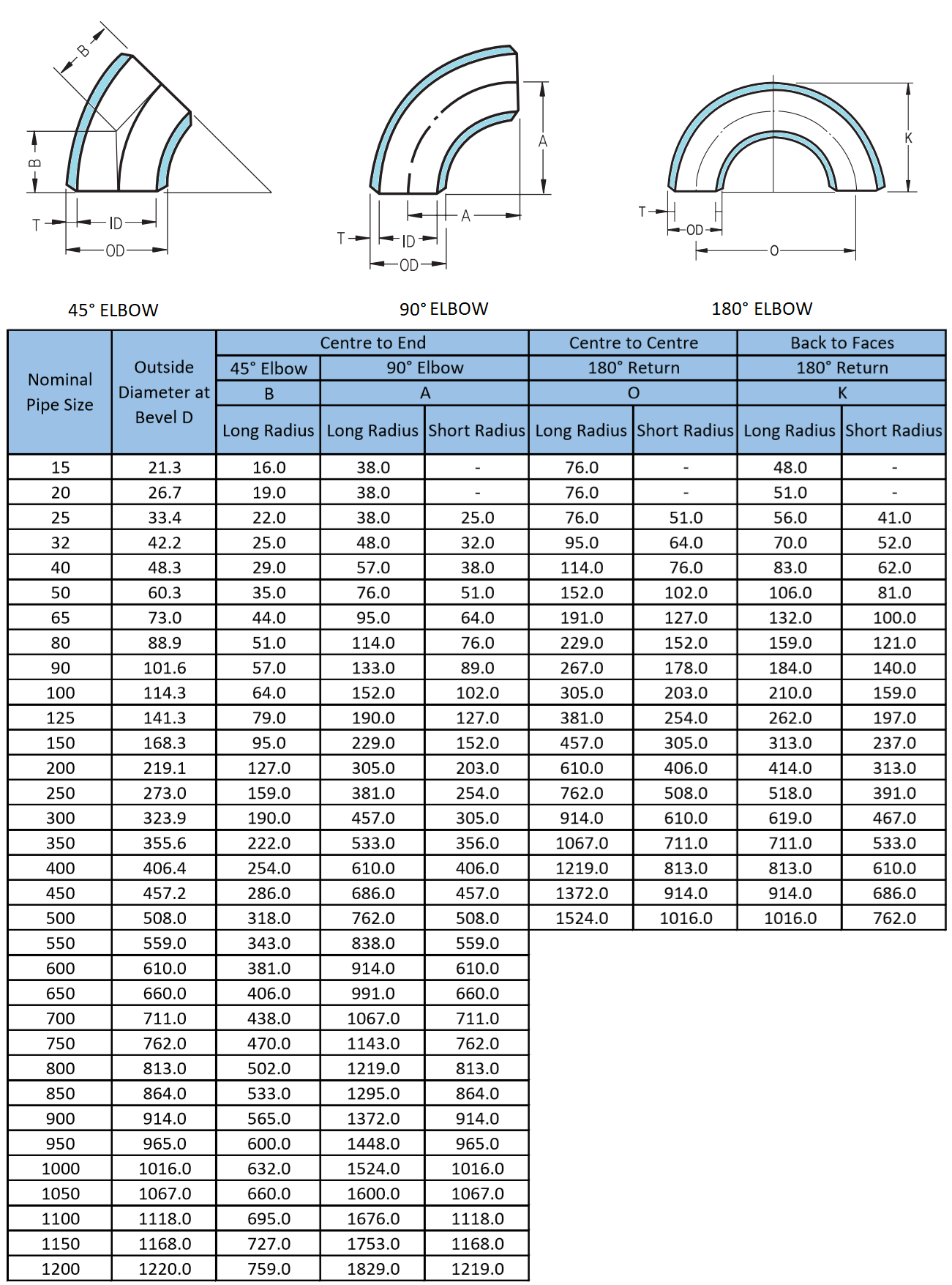
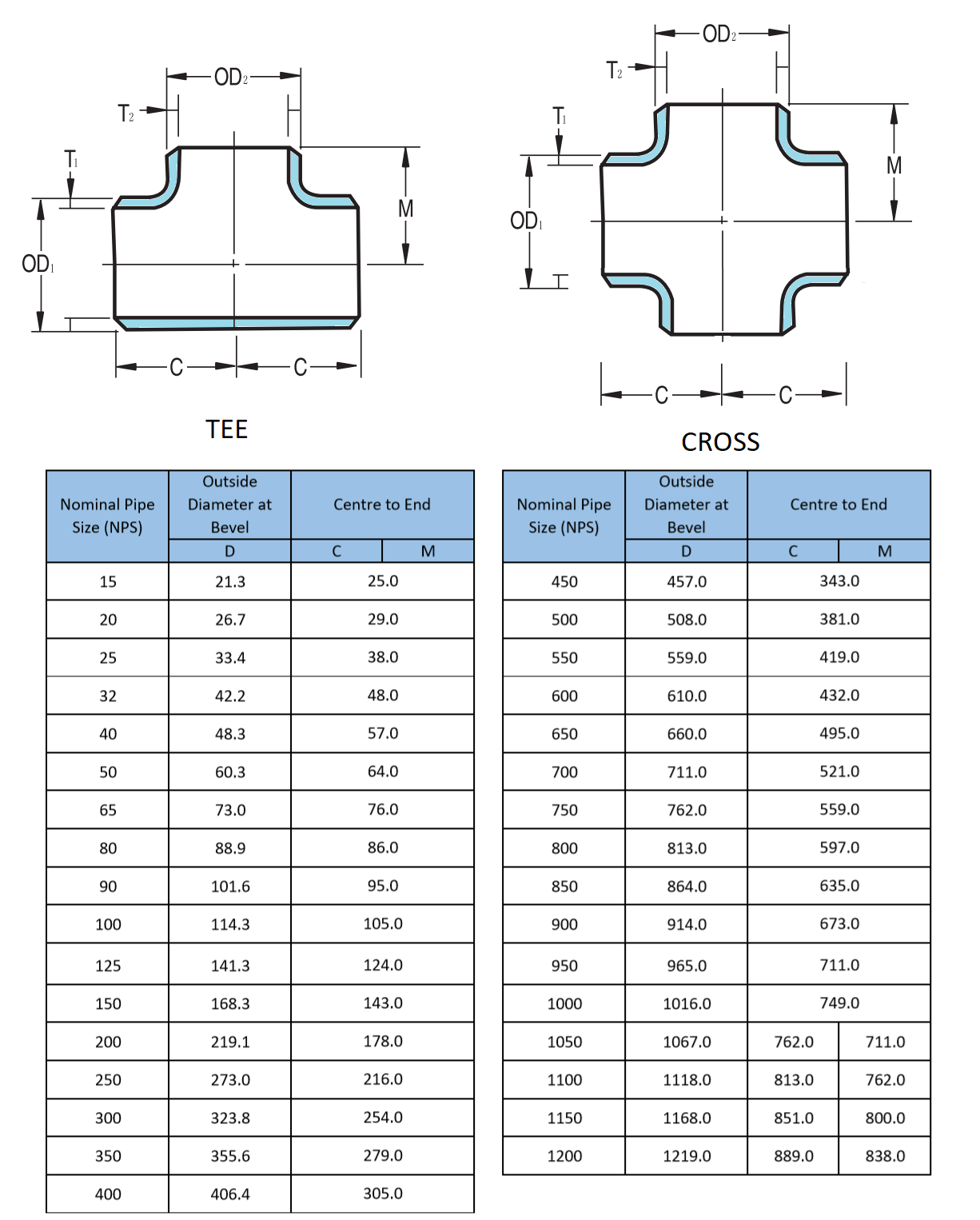
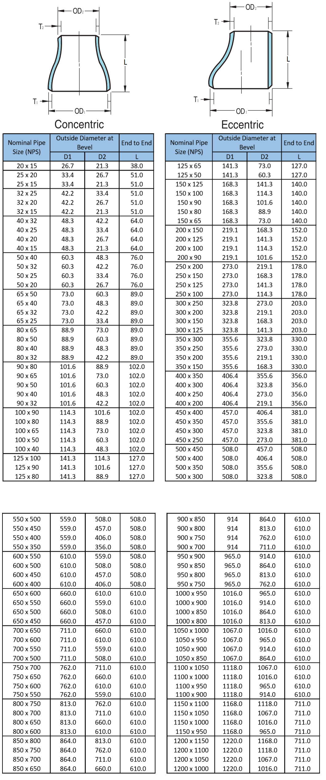
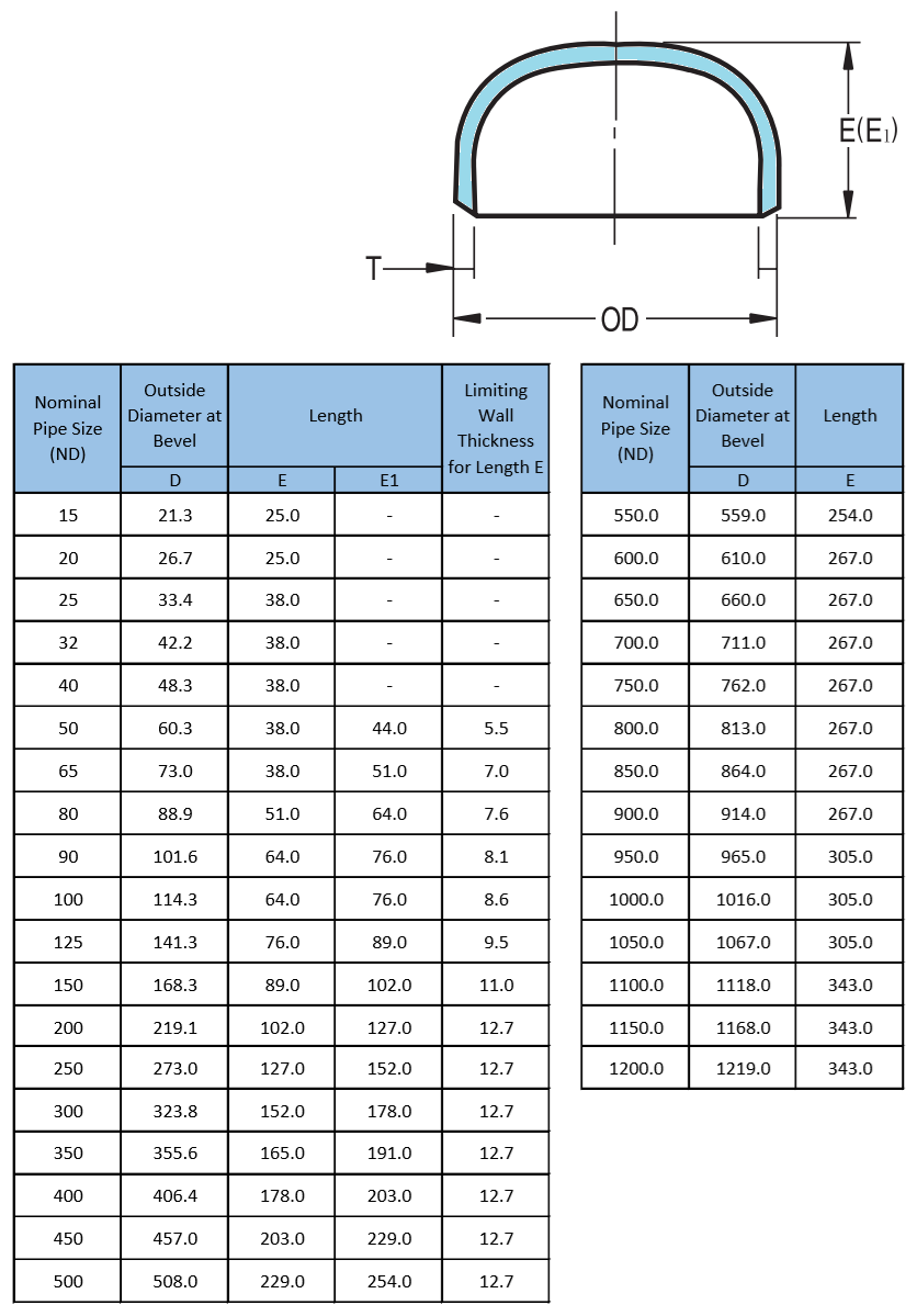
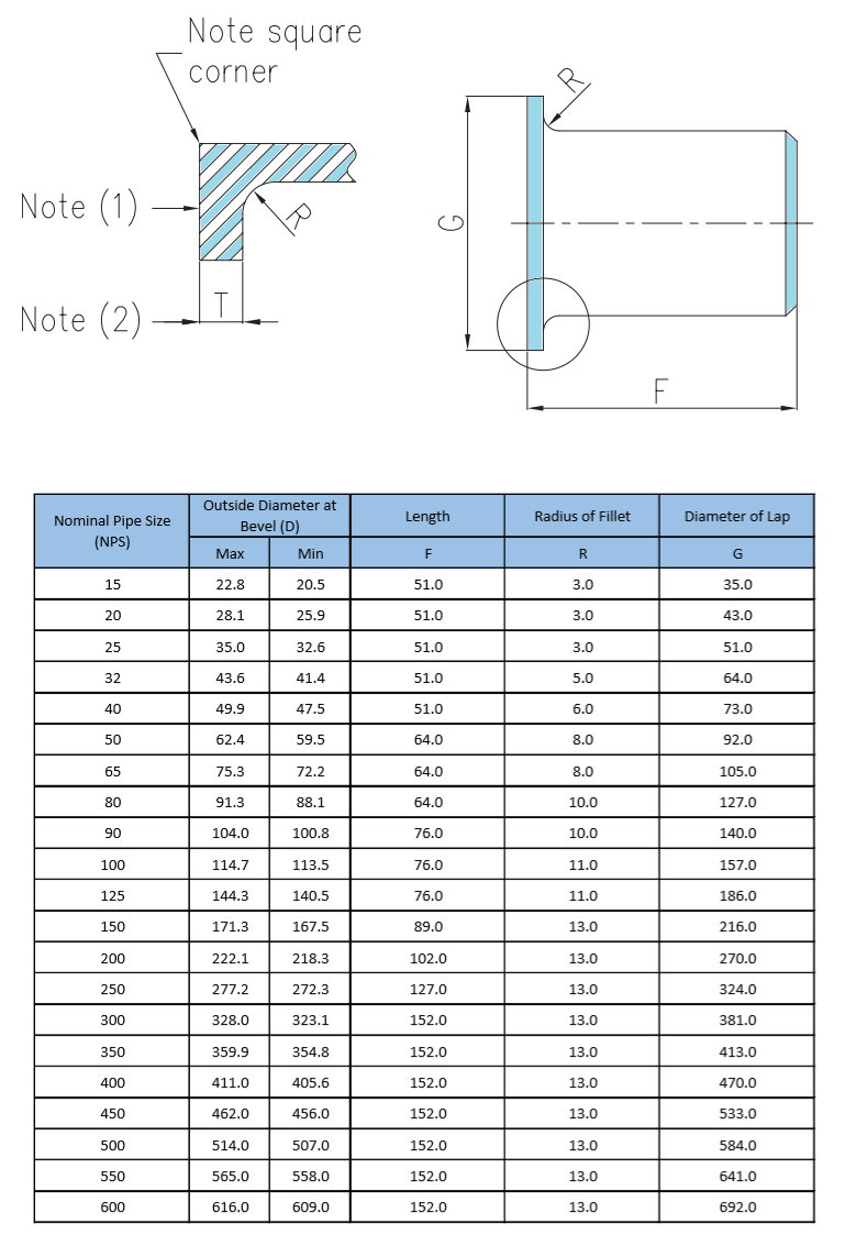
All dimensions are in millimeters.

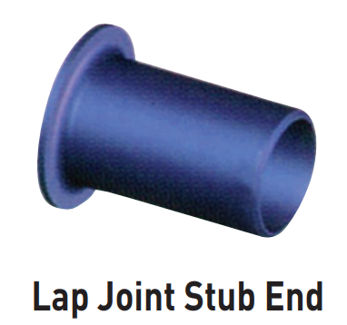
Service conditions and joint construction often dictate stub end length requirements. Therefore, the purchaser must specify long or short pattern fitting when ordering.

NOTES:

1. Gasket face finish shall be in accordance with ASME B16.5 for raised face flanges.

2. The lap thickness, T, shall not be less than nominal pipe wall thickness. 

3. When short pattern stub ends are used with larger flanges in Classed 300 and 600, with most sizes in Classes 900 and higher, and when long pattern stub ends are used with larger flanges in Classes 1500 and 2500, it may be necessary to increase the length of the stub ends in order to avoid covering the weld with the flange. Such increases in length shall be a matter of agreement between the manufacturer and purchaser.

4. When special facings such as tongue and groove, male and female, etc., are employed, additional lap thickness must be provided and such additional thickness shall be in addition to (not included in) the basic length, F.

5. These dimensions conform to the radius established for lap joint flanges in ASME B16.5.

6. This dimension conforms to standard machined facings shown in ASME B16.5. The back face of the lap shall be machined to conform to the surface on which it sits. Where ring joint facings are to be applied, use dimension K as given in ASME B16.5.

Welding End Preparation According to ASME B16.9

End Preparation

Notes:

1. End preparations are in accordance with ASME B16.25 Paragraph 4.2
2. End preparations conforming to customer specifications will be specially manufactured upon consultation.

Dimensional Tolerances According to ASME B16.9

Dimensional Tolerances

Notes:

1. All the dimensions are in mm.
2. Tolerances are equal plus and minus except as noted.

CONNECT WITH US

We’re always looking to connect with people.

CONTACT US

Get in touch with SSE Team and send your inquiries, we’ll be glad to see you.